Embedded Networking and Communication
Assignment
Design and build a wired and/or wireless network connecting at least two processors.Learning Outcomes
Demonstrate workflows used in network design and construction.Implement and interpret networking protocols.
Design Process
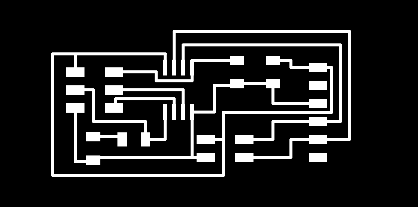
To begin this week, I started off by building the hello.bus.45 board. I wanted to start out with this board to figure out how the boards would connect together and how to get them programmed. Using the process from Week 6 I redrew the bridge board in eagle. Below are the schematic and board layout for the bridge board: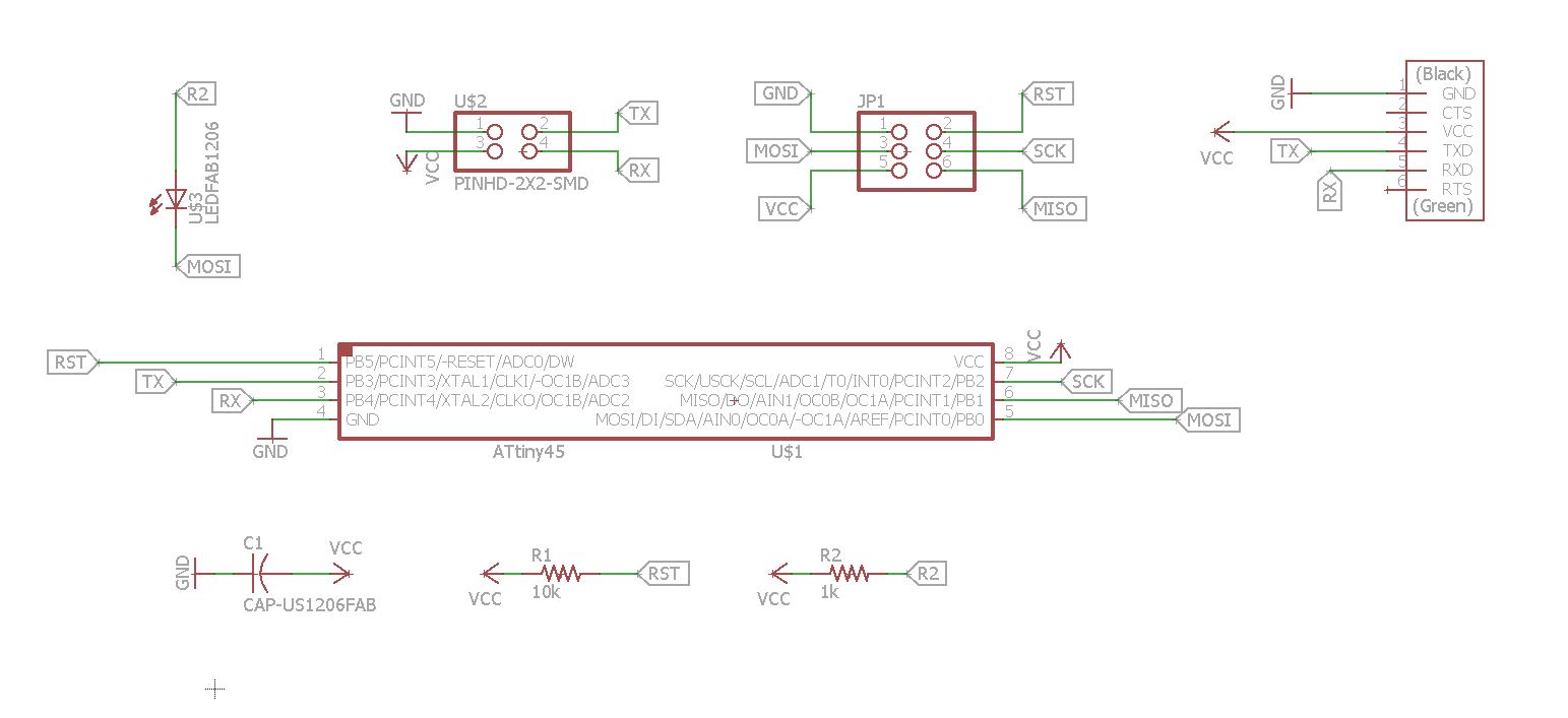
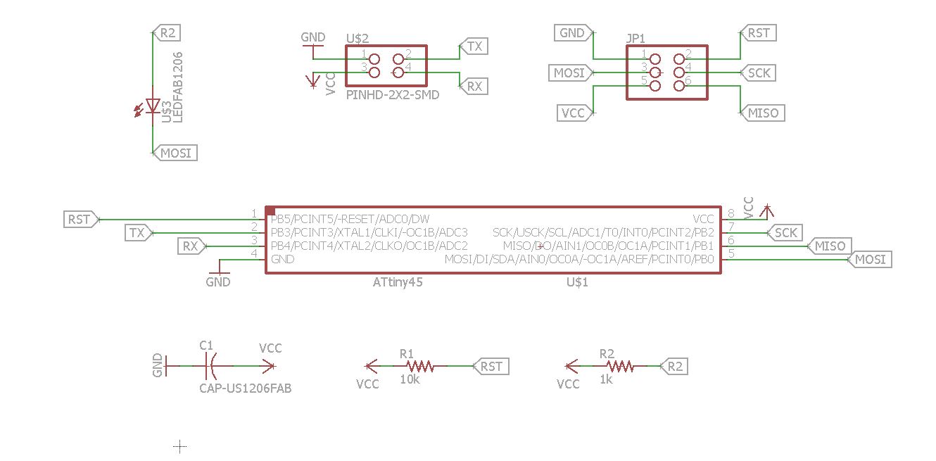
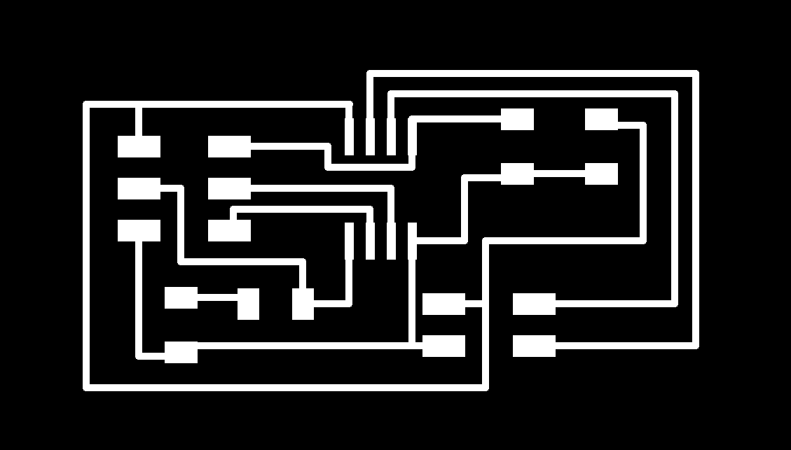
To create the node boards in eagle, I took the same schematic that I used for the bridge board and deleted the FDTI header. I then re-route the connections that were broken from the now absent FDTI. Below shows the schematic and board layout for the node board:
Cutting & Stuffing the Boards
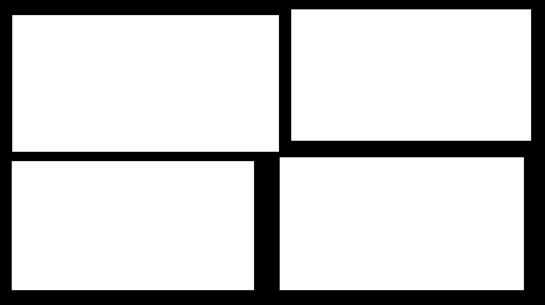
Since I didn't want to cut out four seperate boards (1 bridge, 3 nodes), I laid the boards out in a new file in Paint. I made sure that the copper board was big enough to mill out all four boards and there was plenty of room. Below shows the full cut traces and outline layout for the Roland Modela: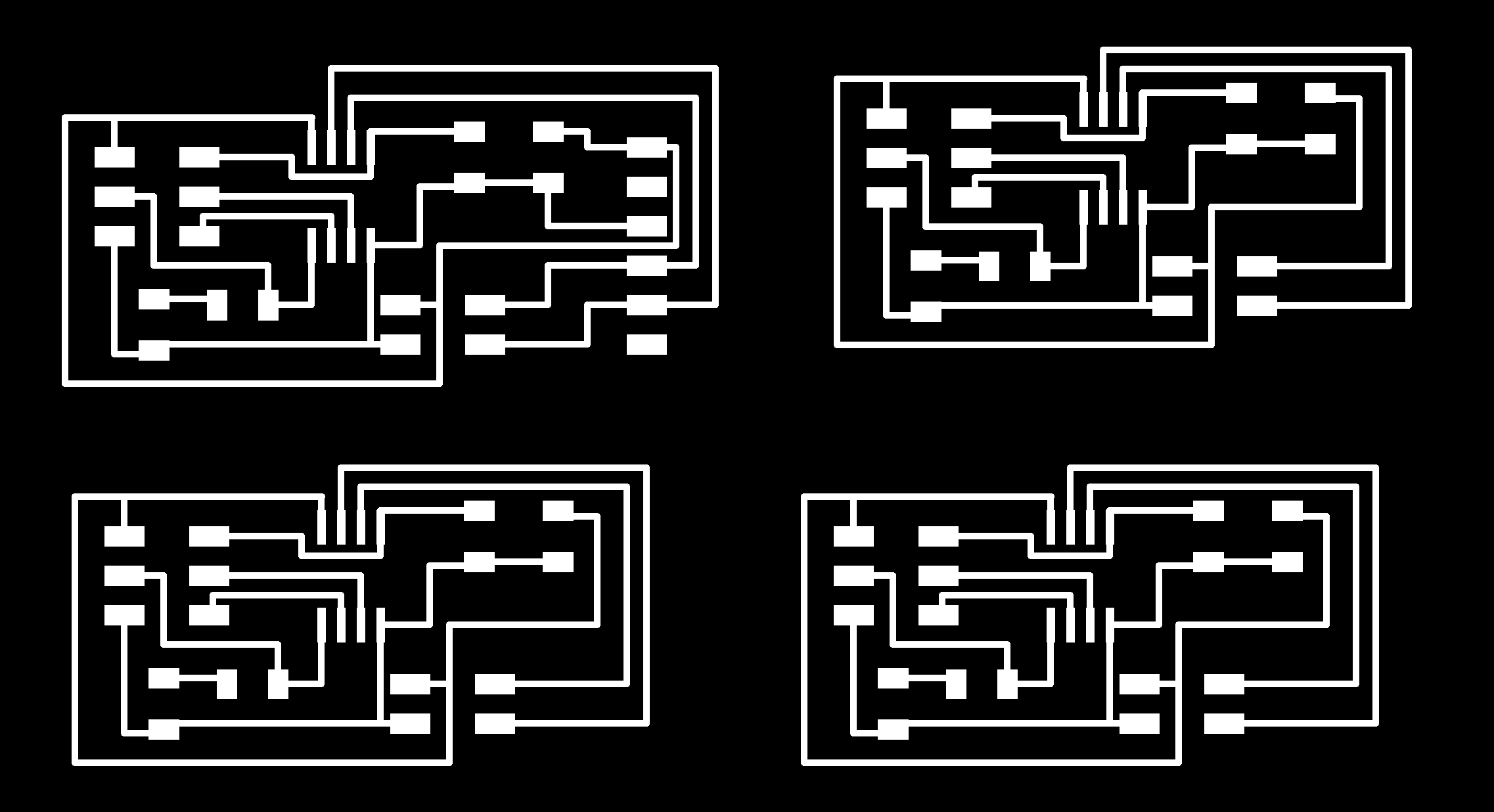
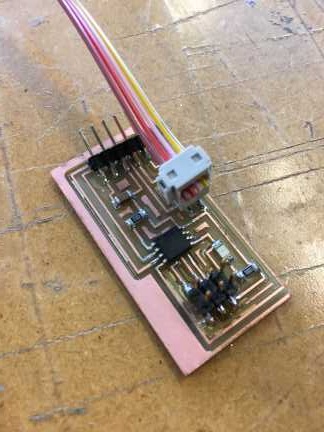
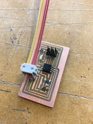
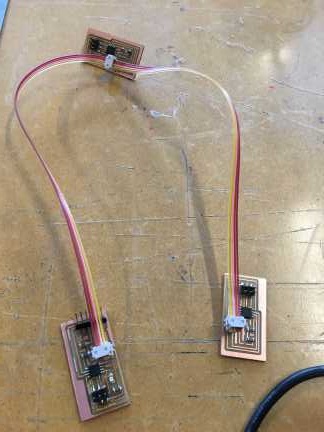
Once the boards were all cut out, I stuffed them all. There are only two nodes instead of three because when I was trying to remove one of the node boards from the Roland Modela I ended up scatching away some of the traces. Below show the bridge board and two node boards ready for programming:
Programming in Arduino IDE
To begin the programming process I started out by trying to program the boards in Arduino IDE. I found the code on the fab academy archive, here, and copied it over to Arduino. I first tried using the AVR MKII as the programmer and attempted to burn the bootloader to the bridge board. Immediately I got a RST fail error. I took a look at my bridge board and saw there was only a little solder on the RST pad for the 2x3 ISP header. I applied more solder to the pad and tried again to burn the bootloader, and again I got an RST fail.I took a closer look at it and saw there was a good amount of solder underneath the ATtiny45 chip that could be causing a short. I removed the ATtiny45 chip and examined the area underneath but could not determine if that was the cause. I ended up soldering a new ATtiny45 chip onto the board.
After trying to burn the bootloader with the new chip on the bridge board and using the AVR MKII it still would not burn. I then switched over to the USBtiny as the programmer to see if that would make a difference. It DID! The bootloader finally burned to the bridge board. I then moved on to the first node board and plugged it into the USBtiny and that board burnt the bootloader, no problem. This was the same case for my second node board!
Now it was time to upload the code. With a push of the "upload" button I was hoping that I would not run into anymore problems. However, I was wrong and the code would not upload. For some reason, I kept generating an error at a certain byte. After some searching on the interwebs, I could not turn up a good solution for why it was giving my this error. It was time to switch my plan of attack.
Programming in Ubuntu
Since Arduino was not working I decided to switch over to Ubuntu and see if I could program the boards that way since a lot of people in the past had success programming that way. I downloaded the makefile and hello.bus.45.c from the fab academy class archive and started up terminal. I then did the following in terminal:1. Changed the directory: Used the command, cd ~/Desktop
2. Entered the command, make -f hello.bus.45.make
3. Entered command, sudo make -f hello.bus.45.make program-usbtiny
To my amazement, it worked! The program ran and I saw a line that read "avrdude done. Thank you." That was a relief. I then moved the USBtiny to the first node and ran commands 2 and 3 again, from above. Before I did this though I went into the hello.bus.45.c file and changed the node id to 1, instead of 0. I did this for the second node as well, changing the node id to 2 this time. The two nodes worked, no problem. Here is a copy of the programming process in Terminal: Terminal Programming
Seeing it Work
Once I knew the code was uploaded onto each board I went back into Arduino and opened the Serial Monitor and made sure it was at 9600 baud. I entered 0 in the command line and all the boards blinked and then the bridge board blinked again! I entered 1, and the boards all blinked and node 1 blinked after. Same for the second node when 2 was entered. My boards were working and I am very happy that they are. Below is a video of the boards blinking. Sorry for the brightness of the room, one of the problems living in the land of the midnight sun :)If video does not play in current browser, please play it here: hello.bus.45 video
Project Files
hello.bus.45.bridge.schhello.bus.45.node.sch
hello.bus.45.bridge.brd
hello.bus.45.node.brd
Full Trace Cut
Full Outline Cut
Successful Program in Terminal